|
|
||
|---|---|---|
| doc | ||
| guide | ||
| qmk-guide | ||
| resources | ||
| src/dactyl_keyboard | ||
| target | ||
| test/dactyl_cave | ||
| things | ||
| .gitignore | ||
| LICENSE | ||
| LICENSE-models | ||
| README.org | ||
| project.clj | ||
README.org
Daktil Keyboard
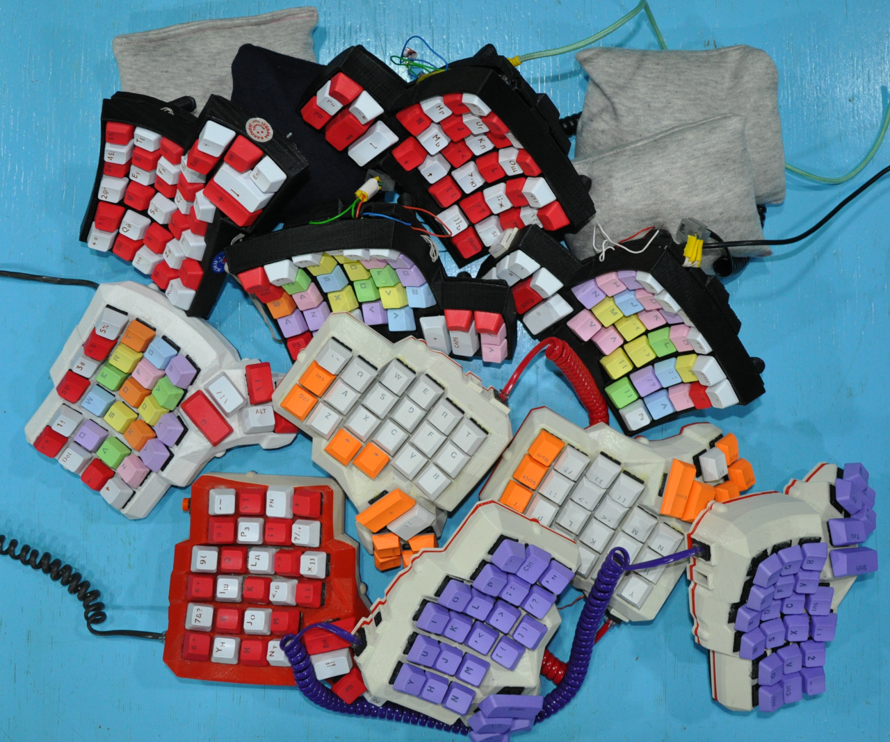
Daktil is a fork of the Dactyl, a parameterized, split-hand, concave, columnar, ergonomic keyboard. A number of them were built at Ljudmila, at the PIFlab workshop.

There's a very interesting talk about the motivation and design of the original Dactyl by Matt Addereth, its creator.
Differences from the original design
The generated model has not changed, but we used an Arudino ProMicro instead of a Teensy Arduino controller. We also did the wiring in columns instead of rows and connected the left and right parts with a spiral telephone cord with 4P4C connectors/cords.
We built some original Dactyls and some Dactyl Manuforms.
Assembly
Parts / materials
- Cherry MX switches
- Arduino Pro Micro (you can / we did / use a clone)
- IO expander (MCP23008)
- 3d print material
- 1N41 diodes (1 for each key / approx. 60)
- two 2,2 kΩ resistors
- two 4P4C telephone jacks and a spiral cord
- enameled wire
Generating a design
Setting up the Clojure environment
Generating the design
- Run `lein repl`
- Load the file `(load-file "src/dactyl_keyboard/dactyl.clj")`
- This will regenerate the `things/*.scad` files
- Use OpenSCAD to open a `.scad` file.
- Make changes to design, repeat `load-file`, OpenSCAD will watch for changes and rerender.
- When done, use OpenSCAD to export STL files
Tips
Printing
Building
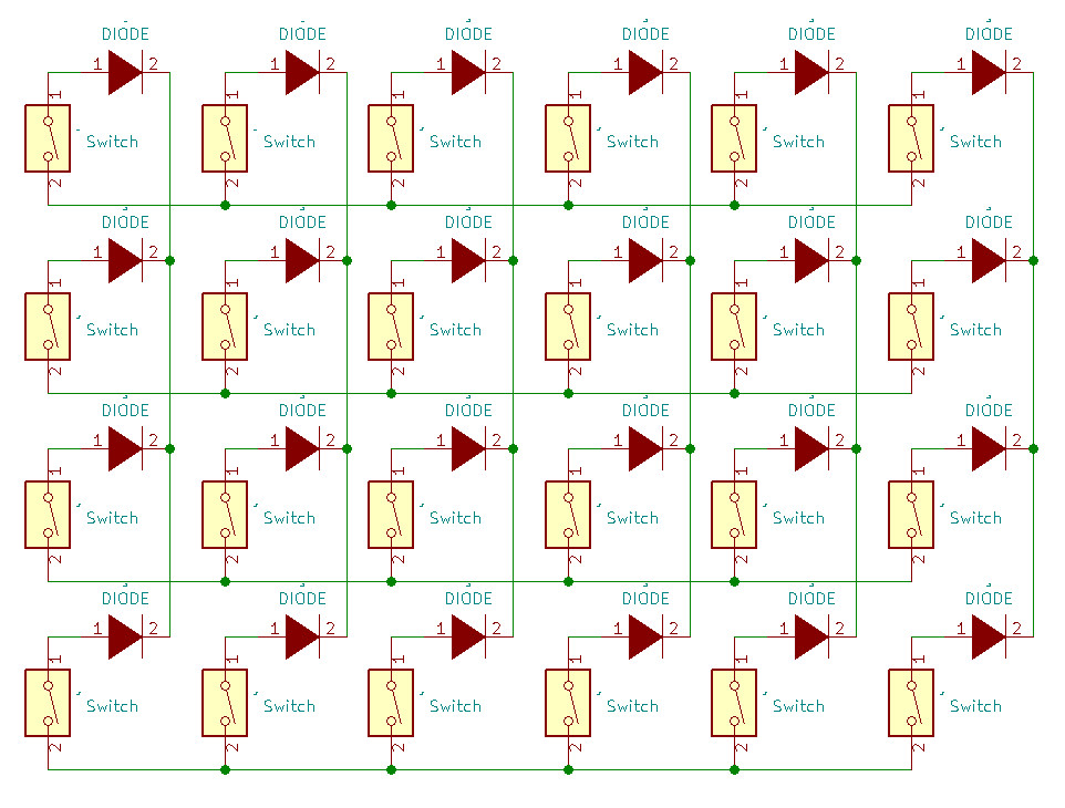
After you've printed the case (either original or manuform), you tuck keyboard switches into the holes. The switches need to be wired together in each half of the keyboard; in principle it is possible to wire it in two different ways. Each switch has two pins, let's call them pin A and pin B. One way of wiring is soldering all pins A in a single row together and all pins B in each column through diodes together. The other way is soldering all pins A in a single row through columns together and all pins B in each column together directly. What we did is soldering rows directly and columns through diodes. The following picture show the wiring that we used:

The schematic shows only 4 rows, but you can have more (or even less) if you want; keep in mind that the thumb cluster is its' own row (the bottom-most). Wiring the thumb cluster is a bit weird and arbitrary, we'll add an example we used soon (TODO). If you screw up the wiring order for the thumb cluster, you can fix it in the matrix (better) or layout of the QMK source before you build the firmware.
Firmware setup
- Clone our QMK repo fork
- Install dependencies (described in readme.md of the repository)
- Run `make handwired/daktil:default`
- Run `make handwired/daktil:default:avrdude`
- Press the reset switch of your keyboard (connect the reset pin and ground)
If flashing failed, it's possible that you don't have a proper (pre-8) version of gcc or some dependencies are missing. Also note that these instructions are for the 5V Arduino ProMicro (clone). It's possible to use a 3.3V one but adjustments need to be made (haven't tried so can't say which exactly).
Original documentation
You can find scans of original documents we used in the doc folder.
License
The source code for generating the models (everything excluding the things and resources directories is distributed under the GNU AFFERO GENERAL PUBLIC LICENSE Version 3. The generated models and PCB designs are distributed under the Creative Commons Attribution-ShareAlike License Version 4.0.